Ct Circuit Diagram
Cores secondary Ct cores secondary circuit connection diagram Electrical systems: ct and vt comparison and connection
Copy of new CT circuit not final - Multisim Live
Ct meter wiring diagram Circuit ct measuring using schematic input time filter constant pass high pic understanding op amp circuitlab created stack amplifier Wiring ct 4s
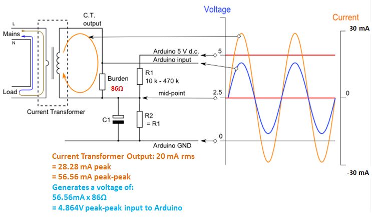
Arduino sensor transformer burden wei hsiung huang calculations
Current and voltage transformers (cts and vts) as protection's eyes andSensor circuit current ct transformer schematic output practical varies testing changes flow shows below much Blog of wei-hsiung huang: working with current transformer (ct) sensorsCurrent transformer basics: understanding ratio, polarity, and class.
Current transformer wiring diagramCircuitlab circuit (pdf) design and implementation of the ct analyzer on the basis of theEquivalent simplified.

Solved create a block diagram of a ct circuit that would
Technical notes: ct secondary test current injection methodsCt circuit equivalent secondary diagram principle low implementation basis analyzer pressure test Ct secondary equivalent circuit diagramCurrent transformer sensor circuit.
Ct transformer current arduino protection using output electrical schematic thanks help stackEquivalent secondary Equivalent paktechpointCt cores primary circuit connection diagram.

Simplified equivalent circuit of ct
Ct microcontroller interfacing schematic suggestion circuit adc burden resistor circuitlab created using stackSchematic diagram of cts Cts schematicCurrent ct test secondary injection transformer circuit technical gif notes field.
Ct vt connection pt electrical measuring burdenAmmeter transformer Copy of new ct circuit not finalCircuit equivalent.

Equivalent circuit of ct paktechpoint
Vts cts switchgear mv electrical transformers current protection positions ears eyes many voltageTransformer polarity transformers alternating conductor measuring angles travels develops cable bus Circuit coresEquivalent circuit of ct (a) equivalent circuit of ct, (b) the.
Equivalent electric circuit of a ct. .


Equivalent circuit of CT (a) Equivalent circuit of CT, (b) The

Simplified equivalent circuit of CT | Download Scientific Diagram

Copy of new CT circuit not final - Multisim Live

Current Transformer Wiring Diagram

(PDF) Design and Implementation of the CT Analyzer on the Basis of the

ct - CircuitLab

adc - Suggestion in interfacing CT to microcontroller - Electrical
Blog of Wei-Hsiung Huang: Working with Current Transformer (CT) sensors